F 125 08 270 S R - SD A - F 2 P
T 100 06 180 S L - D B 2
| Output shaft shape | Axes distance [mm] |
Stop numbers | Indexing angle[°] | Cam curve | Twist direction | Input shaft direction | Install tap face | Install direction | Customized |
|---|---|---|---|---|---|---|---|---|---|
| SShaft type 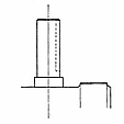 |
40506380100125 | 1 Dwell 0203040506080910122 Dwells 16182024 |
1 Dwell 901201501802102402703003302 Dwells 9045°×2 12060°×2 15075°×2 18090°×2 210105°×2 240120°×2 270135°×2 300150°×2 330165°×2 3 Dwells 9030°×3 12040°×3 15050°×3 18060°×3 21070°×3 24080°×3 27090°×3 300100°×3 330110°×3 |
SMS curve modified sine curve (Standard) CMCV curve modified constant velocity curve TMT curve modified trapezoid curve |
RRight twist (Standard) 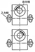 LLeft twist 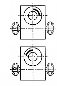 |
SDBoth sides (Standard) 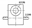 SRRight one side 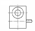 SLLeft one side  |
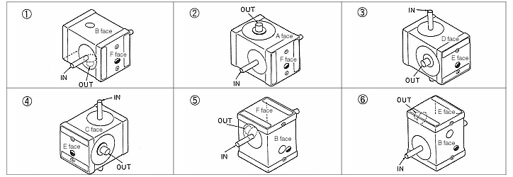
ABCDEF | 123456 | P |
| FFlange type 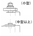 |
506380100125160200 | PPGWith Reducer unit (with CL&B) |
|||||||
| TTable type  |
80100125160200250 | 1 Dwell 030405060809101215161820242 Dwells 30323640483 Dwells 546072 |
DBoth sides (Standard)  RRight one side  LLeft one side  |
* In the input shaft direction code, “s” is omitted for a table type.
* About the tap face, all the 6 faces are tapped.
* For a table type the standard of install direction is 2. When you request other direction, contact us please.
Fig.1 Faces number as below ;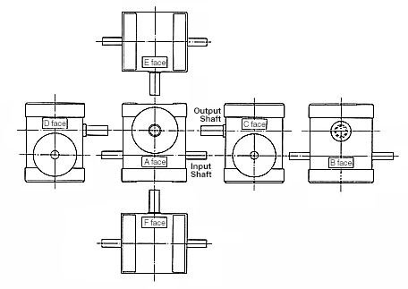
Fig.2 Install direction